
Electrical Design
System Schematics
|
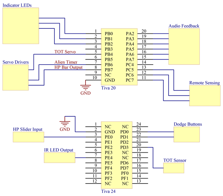
Indicator LEDs
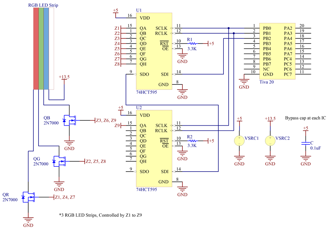
Three individual RGB LED strips (with embedded resistors) indicate where and when "hit" actions are needed from the TATER. Each strip of RGB LED is driven by 3 2N7000 MOSFETs (one for each R/G/B line) connected to digital output pins of two cascading 74HCT595 shift registers. The cascading shift registers enable individual control of 9 (up to 16) MOSFETs using only 3 outputs pins from the TIVA. The logic levels of the '595 pins swing between 0.33V and 4.5V, which is sufficient to directly turn on and off the MOSFETs without the need of any pull up/down resistors or logic-level converters.
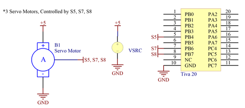
Servo Driver
|
The alien HP bar, motion timer, and TOT-release mechanisms are independently driven by three different servo motors. For each servo, the power line is wired to 5V of the power supply and the signal line is driven by a TIVA PWM-enabled digital output pin. The ground pins are connected together to keep voltages consistent. |
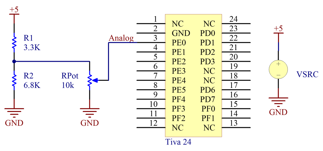
HP Slider
|
At the beginning of each game, TATERs set the alien's HP using a slide potentiometer. A voltage divider scales the potentiometer circuit output between 0V and 3.3V, which is compatible with TIVA analog input pins. The read-in analog signal sets the start-of-game HP, which is displayed to the TATER using a servo motor driving an HP visual. |
Remote Sensing
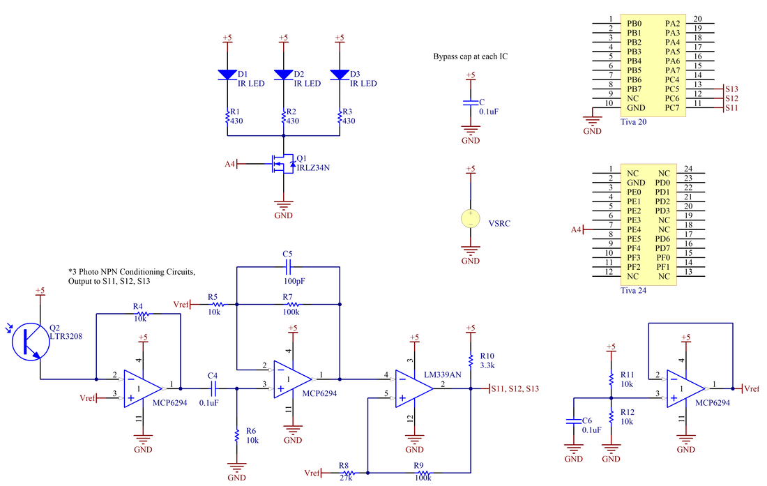
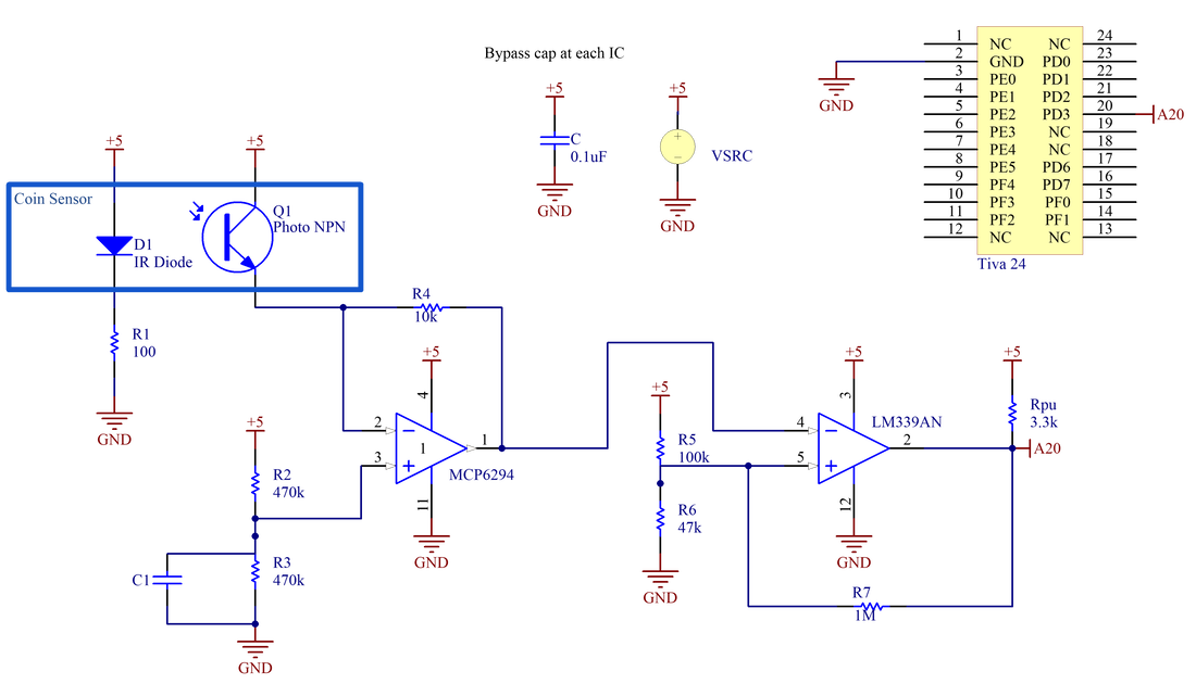
TATERs attack the alien by swiping their hands through IR beams placed in three locations of the arcade. Each location consists of a counter-aligned IR LED and IR phototransistor pair. The IR LEDs are all driven in the low-side configuration using a single IRLZ34N MOSFET connected directly to the TIVA. A PWM signal from the TIVA pulses the MOSFET, which in turn pulses the IR LEDs. The pulsating LEDs changes the expected phototransistor signal to be a set-frequency pulse rather than a constant voltage threshold, which at the right driving frequency (1kHz), is robust to DC bias and low-frequency ambient noise.
The phototransistor circuit uses multiple techniques to amplify the phototransistor signal, reject noise, and react to hand movements in-between the IR LED and IR phototransistor pairs.
First Stage, Trans-resistive Amplification for Photo-Transistor Input:
An op-amp fixes the voltage across the phototransistors to ~2.5V by setting the non-inverting pin (Vref) to 2.5V. The amplifier output voltage is equivalent to the sourced phototransistor current multiplied by -R1 and offset by Vref.

Second Stage, High-Pass Filter with DC bias:
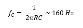
A high-pass filter removes the DC bias and any low frequency noise from ambient light. The driving frequency is set to be much higher than the filter corner frequency and therefore negligibly impacted.
A high-pass filter removes the DC bias and any low frequency noise from ambient light. The driving frequency is set to be much higher than the filter corner frequency and therefore negligibly impacted.
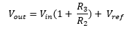
Third Stage, Generalized Op-Amp Circuit with gain of 10
The high-pass filter stage output is amplified by another factor of 10 with a DC offset equal to Vref. The capacitor across the non-inverting terminal and output is used to filter out power fluctuations.
The high-pass filter stage output is amplified by another factor of 10 with a DC offset equal to Vref. The capacitor across the non-inverting terminal and output is used to filter out power fluctuations.
Fourth Stage, Inverting Comparator with Hysteresis:
A comparator converts the amplified analog signal into a digital signal compatible with TIVA digital-in pins. Resistors are empirically tuned so that the comparator reacts to the pulsating IR LEDs without reacting to ambient noise.
A comparator converts the amplified analog signal into a digital signal compatible with TIVA digital-in pins. Resistors are empirically tuned so that the comparator reacts to the pulsating IR LEDs without reacting to ambient noise.

Output: LM339AN output goes HI (5V) when Vin goes above 3.02V; and LO (~0V) when Vin goes below 1.97V.
NOTE: Circuit also uses an op-amp to provide stable Vref: Vref = 5* (10k/(10k + 10k)) = 2.5 V
NOTE: Circuit also uses an op-amp to provide stable Vref: Vref = 5* (10k/(10k + 10k)) = 2.5 V
Audio Feedback
|
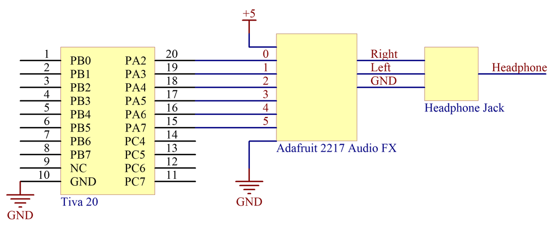
TATERs are rewarded with 5 unique Rick and Morty Audio tracks through an Adafruit Audio FX board. A specific track is played by setting its corresponding pin to LO using the TIVA. The FX board output is connected to a headphone jack for audio playback. |
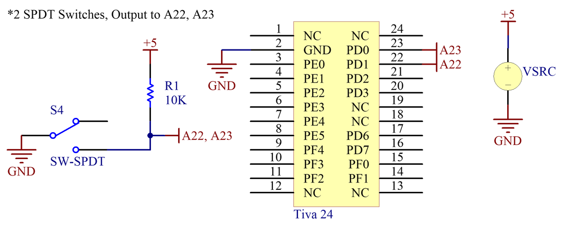
Dodge Button
|
Users dodge alien attacks by pressing one of two arcade-style buttons. Each button, which consists of a single-pole dual-throw switch, is connected directly to a TIVA digital input pin with a pull-up resistor. When the button is depressed, the switch is triggered and the TIVA pin goes LO. |
TOT Sensor
Each game begins with the TATER inserts a TOT into the arcade. TOT-sensing uses a pair of IR phototransistor and IR LED placed facing each other. Due to the close proximity of the sensors and its position away from any ambient noise, the output of the transresistive stage is directly fed to the comparator input.
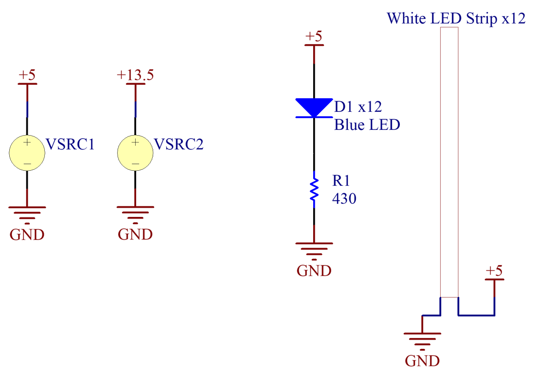
Decorative LEDs
|
Four cool-white LED strips (with embedded resistors) provide ambient backlighting upon power-up of the POTATO. Twelve blue LEDs surrounding the IR beam-break LEDs indicate where users swipe to attack the alien. |
